Knowledgebase
Knowledgebase

After selecting "G-Code Generate" in a SolidCAM or InventorCAM program it should open a text document containing the G-Code for the selected operations. If nothing happens and no text document opens, follow these instructions.

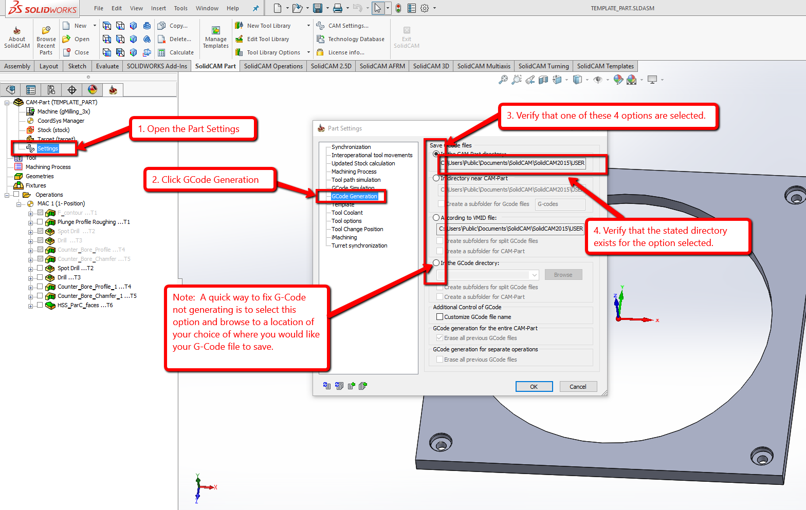
1. Double Click "Settings" or right click and choose "Open."  The Settings icon will be found in the CAM operation tree just below the CordSys Manager and Stock and Target icons.  The Settings icon will have a little wrench next to it.

2. In the Part Settings window, Click "GCode Generation" from the list on the left side.

3. Verify the selection option and the location of where your text g-code file is to save.  Often the issue of no gcode generating is caused by a location that does not exist.

4.  Choose an option and location that exists on your computer.  An easy fix is to select the option of "In the GCode Directory" then Browse to a convenient folder such as "Documents" or "Desktop".

5. Click "OK" then try to generate the G-Code again.


1. Verify the saved location of your existing post processor files.

  • 1.1 Close any open SolidCAM or InventorCAM files but leave Solidworks or Inventor open.
  • 1.2 For SolidCAM users: Open the SolidCAM settings by clicking “Tools” in the main menu area, then “SolidCAM”, and then “SolidCAM Settings
  • 1.3 For InventorCAM users: Open the InventorCAM settings by clicking on the “CAM Settings” button located in the InventorCAM ribbon.
  • 1.4 With the SolidCAM / InventorCAM settings open, select the “Default CNC-Controller” page from the list on the left.
  • 1.5 Verify where your saved location is at for your current post processor files by looking at the top box on the right under “Post-Processor files directory”. Post Processor files should be in a folder named “GPPTOOL”.  Standard install location for the GPPTOOL folder is: C:\Users\Public\Documents\SolidCAM\SolidCAM20XX\GPPTOOL 

2. Completely close down Solidworks or Autodesk Inventor.

3. Open the email sent to you from a SolidCAM Tech Support representative and Save all of the attached files in the same   location that you noted from Step 1.5 above.  (Post files will have a .gpp and a .vmid file extension)  

  • *NOTE*- If the files were sent via a .zip folder then be sure to extract the files first by right clicking and selecting "Extract All".
  • 3.1 When prompted to overwrite existing files choose “Accept”.

4. Re-start Solidworks or Autodesk Inventor.

5. Re-open an existing SolidCAM or InventorCAM project file and confirm the changes made by generating the G-Code.

Right Click on CAM-part in the SolidCAM / InventorCAM feature tree.

Select Send To near the bottom of the drop down menu.

Select either Mail or Folder from the second drop down menu.

Below are the steps to set up and run vericut using SolidCAM/Vericut integration
Initial setup
The very first thing you need to do is create Vericut Machine templates.
There are sample machines and controllers to create your own templates, or you may have been given a template by Cgtech.
You need to establish a templates folder and put your templates in this folder.
Attached is a screen shot called templates folder structure showing an example folder structure. See attached (templates folder structure.png)
Then you need to tell SolidCAM where the templates folder and the Vericut installation folders are. See attached (vericut setup.png)

Project setup
Next you need to set the Vericut Machine template that you want to use for your part verification. See attached (Part settings.png)
After everything is setup and working correctly, right click on operations in the Cam tree and select Gcode Simulators>Vericut Export>All data and Run simulation. See attached (Launch Vericut.png)

after the initial setup you will only need to do the last two steps (Project setup) to launch Vericut when ever you need to run vericut.

Most popular articles 
 
Newest articles